Applied Radiology Focus: 3D ultrasound technology. . .What does it add?


The conventional medical ultrasound (US) image is a remarkable view of a 2-dimensional (2D) slice of a patient's anatomy. While sonographers have become very proficient in manipulating these images in 3 dimensions in their minds, these findings can be difficult to reproduce and impossible to quantify. Three-dimensional (3D) US technology can expand this viewpoint to a registered volume that contains every conceivable plane within the region of interest.
While there is no doubt that there are advantages to volume imaging, does it deliver enough added clinical benefit to justify the increased time, effort, and computational power required to reconstruct the full data set? A review of the basic concepts in US and options for volume data acquisition may aid in answering this question.
Review of US technology
How the image is generated
Ultrasound systems use the transmission and reflection of high-frequency (ultra; >20,000 Hz) vibratory pressure waves (sound) in tissue to form diagnostic and therapeutic images. 1 The mechanical properties of tissues as well as their distance from the source of the sound differentially affect the energy of the sound waves, and this information is used to generate image pixels that vary according to the amplitude of the reflected wave (brightness) and the depth from which the returning echo is received (position). Strong reflections from denser tissues, such as bone or gallstones, image as very bright (white) dots on a monitor screen, weaker reflections from soft tissue solid organs appear as gray dots, and fluids (such as within cysts, blood, or urine) do not reflect sound waves and show as black dots. The higher the frequency of the transducer scan-head, the greater the resolution, but the lower the penetration into body tissues.
The sound waves are generated by the conversion of electric energy into mechanical energy by piezoelectric crystals, which change shape in an electric field. The dimensional change causes pressure waves that resonate at a desired frequency. These crystals also produce electric signals when deformed by pressure from sound waves, enabling the transducer elements to serve as both the source and receiver for the sound waves in pulsed-wave scanning. In continuous wave scanning, different transducer crystals are used for sending and receiving. Transducers can be arranged into arrays that can be shaped to allow for focusing and can be sequentially timed to "steer" the ultrasonic beam. 1
A beamformer is used to control the transducer elements and determine the delay pattern and the pulse train that create the focal point. 2 Several focal points may be used to reach deeper areas in the body (the far field), which require greater transmit energy. The beamformer outputs are usually amplified before being sent to the transducers. The returning waves also are usually amplified, and the output from each element is stored, aligned in time, and coherently summed in another beamformer before conversion to digital signals for display on a monitor (digital beamformers sample the analog signals, store them, and then sum them digitally). 2
How volume image data are acquired
To acquire 3D (or volume) US data, one must devise a method for adding position and orientation information to the 2D image to accurately determine spatial location. This can be done by using mechanical scanning systems that move in a fixed coordinate system, freehand methods with or without position-sensing devices, and 2D transducer arrays. 3,4
Mechanical scanners-- Mechanical scanning methods use a motorized assembly to rotate or translate the transducer within a fixed geometric grid. This allows the 2D US images to be acquired at pre-defined spatial or angular intervals. Al-though mechanical scanning methods are cumbersome for the user, the precise localization they provide allows very accurate 3D reconstructions that are available immediately after data acquisition. 4,5 Mechanical transducer assemblies may be integrated or external. Integrated systems place a specialized transducer within the motorized assembly housing. Such systems are usually smaller than those using external assemblies but require a dedicated US system. Integrated systems are popular in obstetrics. 4 External systems can be attached to any conventional transducer and work with a standard US ma-chine. These systems are popular in vas- cular, breast, and prostate imaging. 4
Three common types of mechanical scanning motion are linear, tilt, and rotational (Figure 1). Linear scanning moves the transducer along a set of tracks at a constant rate and can allow adjustment of the interval between parallel images for proper sampling. If the transducer is tilted, 3D color and power Doppler scans are possible. In tilt scanning, the transducer is rocked side-to-side at a constant rate in a fan-shaped pattern, producing a volume image. This technique is appropriate for image acquisition through a small acoustic window. 6 However, the resultant wedge shape produces images in the far field that are farther apart than those in the near field, with a resultant decrease in resolution with increasing depth. 5 Rotational scanning turns the transducer along its central axis, and produces a cone-shaped imaging volume. This method may have a similar loss of resolution in the far field, as does tilt scanning, and because the images intersect at the axis of rotation, any motion can cause artifacts at the center of the 3D image. 5
Freehand systems-- Freehand systems may be untracked or tracked with a position sensor attached to the transducer. In untracked scanning, the operator moves the transducer at a preselected linear or angular velocity. Although this method may be a convenient way to produce a 3D image for visualization of anatomy, geometric distance or volume measurements are not accurate and should not be attempted. 4
Tracked freehand methods use a sensor attachment to provide information on the exact orientation and angulation of the transducer. There are at least 4 methods to track the freehand transducer: Magnetic, 5 acoustic, 5 optical, 7 and articulated arm. 5 Tracking with magnetism involves detecting changes in a spatially varying magnetic field that is produced by a transmitter attached to the transducer. The detector contains 3 orthogonal coils that measure magnetic field strength. The relative position of the transducer can be determined by measuring the local magnetic field. However, the detector must be positioned close to the transducer to minimize electromagnetic interference, and there should be no ferrous or conductive metals, including pacemakers, in the vicinity. 5,6 Acoustic systems use timed, pulsed sound waves from spatially fixed emitters that are mounted on the transducer. The relative distance and timing of the emitted sound waves that are received by microphones located above the patient are used to calculate the position of the transducer. Optical systems use a tracking method similar to that of the acoustic systems. A set of infrared-light-emitting diodes (LEDs) is mounted on the transducer, and the emitted light is detected by cameras fixed above the field of interest. Although this method is more accurate than the magnetic tracking method, it requires a line of sight from the transducer-mounted LEDs to the camera. 8 An optical tracking system has been used to coregister the US transducer and the thermal applicator in the thermal ablation of focal liver lesions. 7 Articulated arm systems use potentiometers located in the joints of a mechanical support structure to record the position of the transducer.
2D transducer matrix arrays-- Mechanical scanning and freehand scanning methods move the transducer crystal to produce 2D images that are reconstructed in 3D volume. Matrix, or 2D, transducer arrays use a stationary 2D transducer with a built-in beamformer to electronically sweep the pyramidal US beam over the area of interest to create real-time 3D images, also called 4-dimensional (4D) imaging. 4 Although the transducer remains stationary, sophisticated software controls the firing of many thousands of equal-sized, piezoelectric crystal elements to steer the ultrasonic beam in a phased-array manner. 6 Matrix transducers may be added to some US units as an upgrade, but the machine would have to have the hardware design to do 3D imaging (personal communication, Dr. Gerald Marx, December 2005).
Image processing and display
Data reconstruction methods-- The final 3D image must be reconstructed from the acquired 2D planar data in a series of steps involving the following: conversion of digital data into a 3D coordinate system; interpolation, or the assigning of gray-scale values for any data points not sampled (ie, located between the acquired planes); segmentation, or delineating the region of interest for reconstruction; and image enhancement. 5,6 Image reconstruction can be by feature-based methods, such as surface rendering or multiplanar reformatting, or by volume-based methods, such as volume rendering, which is voxel (volume pixel)-based. Feature-based methods use segmentation of surfaces or volumes to outline areas of interest that are to be distinguished from the surrounding anatomy and displayed as 2D images with 3D clues. This method requires less 3D data, produces fast reconstruction times, and can have artificially enhanced contrast between structures. However, subtle differences in tissue can be lost or distorted. In addition, manually assigning boundary descriptions can be tedious. Voxel-based methods assign each pixel to a volume grid, retaining all original image information. This method creates very large data sets (which require vast computational power) but allows for different rendering and image display techniques.
Surface rendering-- In surface-rendering techniques, the operator marks the boundaries of the region of interest. 5 This can be a manual process or can be computer assisted through the use of special algorithms. The computer next uses points and lines, or vectors, to draw wire-frame representations of the area. The resulting boundaries are shaded and illuminated to show surfaces, which are viewed as opaque structures. Surface rendering is well suited to displaying the physical features of fetuses (Figure 2) and the sizes and spatial relationships between objects (such as tumors) but does not show internal structures. Because it manipulates less data, this vector-based method produces images quickly and with less computational demands compared with voxel-based imaging techniques, such as volume rendering.
Multiplanar reformatting-- In multiplanar reformatting, various intersecting or consecutive 2D planar surfaces are generated for viewing. If 3 orthogonal planes are chosen, the anatomy will be displayed in correct relative orientation. In a variation called texture mapping, 5 planar surfaces are displayed on a geometric form, such as a polyhedron, to provide a 3D effect. The model can be rotated or "sectioned" as desired by moving any face of the polyhedron to provide views throughout the region of interest. In addition, the extracted planes can be shown side-by-side with intersecting lines that are used to retain relative 3D orientation.
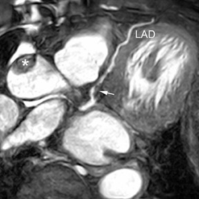
Volume rendering-- In volume rendering, the entire volume of data, and not just selected planes, can be viewed as desired. This is done by using a technique called ray casting. 4 In this method, an algorithm produces a projection, or ray, that is directed through a row of vox-els in a set of image data. As the ray encounters each voxel, it assigns it a value according to a specific algorithm that first weights the volume elements (for example, by using a multiplication factor) and then sums them to produce varying degrees of translucency. This method allows for the display of many different effects such as maximum intensity projection images wherein only the voxel with the greatest intensity along each ray is displayed. 5 In this way, internal features can be visually explored throughout the entire data volume (Figure 3).
3D compared with 2D US:Advantages and limitations
Advantages
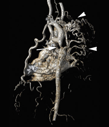
Many physicians would agree with Dr. Beryl Benacerraf, Clinical Professor of Obstetrics, Gynecology, and Radiology at Harvard Medical School, Boston, MA, who believes that "the difference between volume 3D and just taking one slice of image as you see it is mind boggling." A lot of Dr. Benacerraf's research is based on the concept of making 3D US a standardized screening tool that could do body imaging similar to computed tomography (CT) (Figure 4). "Up until last year, we were making pretty baby face pictures, and nobody really had a handle on what 3D was going to be useful for." Ultrasound has been losing market share to the more glamorous imaging modalities, such as CT or magnetic resonance imaging (MRI). "If you look at the displays that CT and MRI are coming up with, they are incredibly innovative and amazing. It leaves ultrasound in the dust. No wonder that the people coming out of residency right now want to work with the new and sexy stuff." Dr. Benacerraf believes the new ability to do 3D imaging has put US back into the competitive arena. "It's faster, it's cheaper, and it has a lot of advantages."
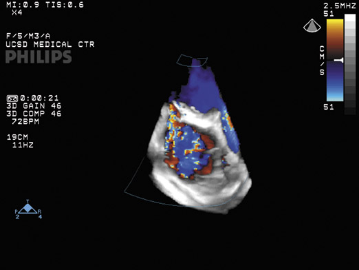
One of the advantages of 3D US is that a surgeon can visualize the anatomy in a manner similar to the actual views encountered during surgery, which facilitates surgical planning. "3D will present to the surgeon how the heart would look at the time that the chest is opened," notes Dr. Lang, Director of Noninvasive Cardiac Imaging Laboratories at the University of Chicago Hospitals. Three-dimensional US can also be used during the surgery to monitor the procedure and its results. Three-dimensional color Doppler, for example, can show the jet in 3 dimensions to characterize mitral valve regurgitation (Figure 5) or leakage of valve repair procedures.
Three-dimensional US examinations spare the patient the risks of radiation exposure. According to Dr. Gerald Marx, Associate Professor of Pediatrics, Harvard School of Medicine, and Senior Associate in Cardiology at Boston Children's Hospital, "I think we have moved into an arena in which we clearly rarely do catheterization for diagnostic purposes. But I think, even further, with 3D analysis and 3D volume analysis, we will be able to obviate that radiation exposure." He notes that more and more angiography is done with MRI. "The difference is that with MRI, although the acquisition time is getting much shorter, infants and even young children have to receive general anesthesia, whereas we hope, for an infant or a young child, we can make those acquisitions in only 4 heartbeats and do not need general anesthesia to do a 3D echocardiogram." Unlike MRI, with US imaging there is no strong magnetic field and no contraindications for ferromagnetic instruments or equipment. In addition, contrast agents are not required for 3D US.
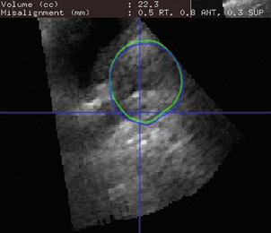
Dr. Eric Berthelet, Radiation Oncologist at British Colombia Cancer Agency, Vancouver Island Center, and Clinical Associate Professor, Faculty of Medicine, University of British Colombia, BC, Canada, is studying 3D US with optical sensors on the transducer to track the movement of the prostate gland during radiotherapy and compare accuracy with the commonly accepted method of adjusting treatment by the use of gold fiducial markers (Figure 6A). He thinks that one of the advantages compared with 2D US images, which have to be registered with the pretreatment CT scan, is that the 3D US images that are obtained daily can be registered to the reference US (Figure 6B). "It takes away a little bit of the variability that is associated with registering different image modalities-registering, for example, US and CT, or US and MRI." The current use of gold markers requires an extra appointment, is an invasive procedure associated with discomfort to the patient, and can cause bleeding and infection. Dr. Berthelet hopes that using US in this application will spare patients these risks. He noted that another application is to assess response to treatment of patients with head and neck cancer. Volume US imaging can track the response of the lymph nodes in the neck region and help decision making for treatment field reduction or dose modifications.
Disadvantages
The main disadvantage of 3D US appears to be the extra time required for image reconstruction and rendering. Regarding real-time 3D images, Dr. Marx notes that "right now, the biggest limitation is that it does take additional time to analyze and reconstruct the pictures-maybe a couple of minutes to 15 to 20 minutes." Currently, a similar analysis done in an MRI suite or a CT suite is considered to be part of the study. But this is not the case for ultrasonography. "In our laboratory, we do anywhere from 50 to 70 studies a day, and it's very hard to have that additional time to do the offline analysis." Dr. Marx hopes that medical insurance payers will see the importance of volume echocardiography and reimburse for these analyses.
There is a learning curve involved for both physician and sonographer who begin to perform 3D US imaging. Because there are many options for viewing the region of interest, there are more controls. Instead of acquiring a plane of data, for example, real-time systems acquire a volume of data. This imaging method requires vast computational power and data storage. In addition, motion artifacts can be a problem. According to Dr. Benacerraf, there is also some loss of image quality with any reconstruction, but this is improving with new advances in imaging technology.
The medical community is attempting to create some guidelines for standardization of 3D views and patient positions. Dr. Marx has been working on a position paper in echocardiography on generalized 3D imaging. "This is something that is realized and recog-nized-that we have to start developing a nomenclature or language as to how this should be best performed, best understood, and best communicated between people doing the procedures."
Sampling of clinical trials of 3D US
The advantages of 3D US have been exploited in a number of clinical applications, from image-guided therapy, field placement verification in radiotherapy, and intraoperative imaging to measurement and quantification of organ function, tumor vascularity, and anatomic volumes. Just a few of the many and diverse clinical trials in which 3D US imaging has shown promise are in the fields of cardiology and vascular medicine, obstetrics and gynecology, and ophthalmology.
Cardiology and vascular medicine
Three-dimensional US excels at diagnostic imaging of the heart, according to Dr. Roberto Lang: "The heart is a 3-dimensional object, so it makes sense to image it as a 3-dimensional object." Dr. Lang uses real-time 3D US to obtain dynamic volumetric information on cardiac function. "When you image the heart in 2 dimensions, you make assumptions about the cardiac volumes based on a geometric model, rather than take actual measurements." He and his colleagues recently tested the feasibility of volumetric quantification of global and regional ventricular function by using 3D echocardiography. 9 In this study, global and regional left ventricular volume time and wall motion curves were obtained for 30 patients and analyzed according to 3 protocols that compared the results with 2D US and MRI findings. They concluded that 3D US findings correlated well with MRI data and could differentiate populations by left ventricular function. Automated detection of regional wall motion abnormalities agreed with 2D US findings in 86% of segments.
Dynamic 3D US imaging of the fetal heart has been done by using tissue Doppler data to calculate a gating signal. 10 In this experimental study, B-mode cineloops were synchronized with tissue Doppler gating signals. The dynamic cardiac reconstructions thus produced were of high quality, and these, along with classical 2D views, were judged to be adequate for clinical use.
Three-dimensional power Doppler US has been used to quantify arterial stenosis and may become an alternative to X-ray angiography. 11,12 A study comparing digital subtraction angiography (DSA), 2D color Doppler sonography (CDS), and 3D reconstruction for assessment of internal carotid artery stenosis in 49 patients found good agreement between DSA and 3D CDS (mean sensitivity of CDS, 93%; specificity, 82.5%; positive predictive value, 82%; negative predicative value, 98%). 12
Gynecology and obstetrics
In addition to the well-known application of imaging fetal development, 3D US can be used for imaging female reproductive anatomy. After commenting that looking at the fallopian tubes is a lot easier with reconstructed views, Dr. Benacerraf continued, "With 2D images, all of the views of the pelvis are acquired through the transvaginal portal of entry, whereas if volume data are acquired, you can reconstruct the pelvis in whatever orientation you want, making the portal of entry irrelevant."
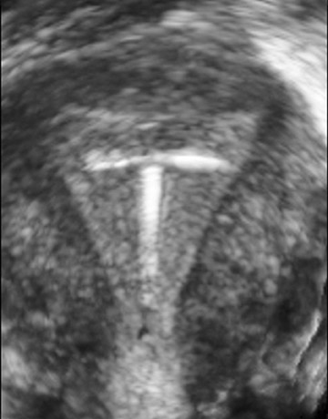
Infertility specialists need to evaluate the shape of the uterus for any abnormality that might lead to reproductive failure, but uterine shape abnormalities are undetectable by regular 2D US. In the past, an MRI study was required, but now abnormalities in uterine shape can be diagnosed with 3D US (Figure 7).
The reproducibility of 3D US findings in gynecology have been confirmed by several recent studies. Yaman and colleagues 13 found that measurement of endometrial volume was more reproducible by 3D US than by 2D US in women with postmenopausal bleeding. Salim and coworkers 14 found that interobserver and intraobserver variabilities were within satisfactory limits of agreement in the diagnosis of congenital uterine anomalies.
The structure and vascularity of the ovaries can be easily assessed with 3D US. Kurjack and colleagues 15 compared 3D sonography and power Doppler imaging with standard 2D transvaginal gray-scale and color/power Doppler modalities to assess suspected ovarian stage I cancer in 43 patients in a retrospective analysis. They found that combined 3D sonography and power Doppler achieved a diagnostic accuracy of 97.7% compared with only 69.8% and 86.1% for 2D gray-scale and combined 2D gray-scale and color Doppler, respectively.
Ophthalmology
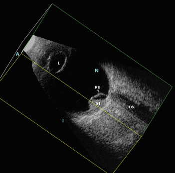
Three-dimensional US reconstruction of eyes with retinoblastoma were analyzed as to provide unique planar views that were previously unavailable with 2D instruments (Figure 8). Oblique and coronal images have been shown to be indispensable in evaluation and follow-up after treatment. In an initial experience reported by Finger and coworkers, 16 volume US imaging of 5 eyes of 3 children allowed the discovery of new oblique and coronal views that could be used to determine relative distances between tumors; simultaneous viewing of these tumors was not possible with ophthalmoscopy. In addition, interactive sectioning of the ocular volume, which is not possible with 2D US, allowed differentiation of the optic nerve from orbital shadowing caused by intratumor calcification.
In another report by Finger and colleagues, 17 3D US was used to measure tumor volumes of choroidal melanomas (Figure 9). They evaluated 50 3D US images and found that derived measurements of tumor volume correlated well with standard tumor measurement techniques. They believed 3D US volume measurements better accounted for tumor geometry than did calculated estimates of tumor volume based on basal area and height, and they concluded that volume US could be used for measurement of choroidal melanomas.
Recently, this same group explored the use of coronal C-scan images to measure optic nerve sheath diameter in healthy volunteers, patients with optic nerve sheath meningiomas, and in 1 patient with retinoblastoma. 18-20 The automated measurements were similar to those obtained with MRI and CT, and the authors conclude that 3D US may have a role as a screening tool for this application.
Future trends
Although 3D US imaging is gaining popularity, the extent to which it will become integrated into routine US examinations may be related to the time required for volume calculations and various data set reconstructions. Dr. Marx believes that automation is the key to overcoming these problems. He would also like to see miniaturization of the matrix array transducer to allow 3D imaging by use of the transesophageal echocardiography probe, or in intravascular probes that could image inside the heart itself. In Dr. Marx's ideal future, wireless technology would accompany this new intraorgan scanning. "Certainly, having a miniaturized transducer that could both send and receive electronically and communicate with the US machine via wireless technology would be terrific."
Once surgical instrumentation is also miniaturized, robotic assistance could be exploited along with 3D ultrasonography to assist with the repair of difficult-to-access anatomic abnormalities. For example, surgery on the beating heart would prevent the need for heart-lung bypass machines. A global "road map" could be obtained of the heart and its great vessels and extracardiac structures with CT or MRI, and real-time monitoring could be provided by 3D echocardiography.
Lastly, fine molecular details of living subcellular structures at nanometer resolution may become possible when US waves are substituted for laser beams in futuristic holographic applications (see sidebar, "3D ultrasound holography").
Conclusion
New 3D ultrasound technology brings the ability to accurately reproduce almost any view of the anatomy with precision. The resultant image display capabilities allow physicians to plan and monitor invasive therapeutic procedures. Because anatomic orientation is retained, accurate volume measurements can be made. Patients can be spared the radiation exposure associated with CT, the discomfort, expense, and strong magnetic fields of MRI, and the morbidity associated with more invasive diagnostic procedures. Because it is possible to view any plane in the image set, even views that would be difficult or impossible with 2D US can be obtained with subsequent 3D image reconstruction. Upgrading conventional 2D machines to 3D imaging may be possible with the addition of 3D transducers and additional software. It would appear that this new technology is well worth the increased time, effort, and computational power required to bring its full capabilities to bear on modern clinical imaging.
References
- Anaesthesia UK. Ultrasound and physical principles. Online document. Available at: http://www.frca. co.uk/printfriendly.aspx?articleid=298. Accessed December 2005.
- Brunner E. How ultrasound system considerations influence front-end component choice.Analog Dialogue.2002;36(3):1-4.
- 3D ultrasound imaging. Available at: http:// www.acad.polyu.edu.hk/~rcbus/3DUltrasoundImag- ing/Introduction.htm. Accessed December 2005.
- Fenster A. 3-dimensional ultrasound imaging.Decis Imaging Econ.2004. Available at: http://www. imagingeconomics.com/library/200412-08.asp.
- Downey DB, Fenster A, Williams JC. Clinical utility of three-dimensional US.RadioGraphics.2000;20: 559-571.
- Lozano JL. Three-dimensional echocardiography: Off-line and real-time. Available at: http://ric.uthscsa. edu/personalpages/lancaste/DI2_Projects_2004/JL_Project.pdf. AccessedDecember 2005.
- Lemor R, Tretbar S, Hewener H, et al. An ultrasound-based integrated system for navigation and therapy control of thermal ablation therapies. Presented at the Scientific Assmebly of the Radiological Society of North America, November 2005, Chicago, IL. Abstract.
- Hossack JA, Ha JS, Sumanaweera TS. Quantitative, free-hand 3D ultrasound imaging based on a modified 1D transducer array. 2001 SPIE Medical Imaging Conference. Available at:Hobbes.ee.virginia.edu/ultra/pdf/SPIE_4325_54.pdf. Accessed December 2005.
- Corsi C, Lang RM, Veronesi F, et al. Volumetric quantification of global and regional left ventricular function from real-time three-dimensional echocardiographic images. Circulation. 2005;112:1161-1170.
- Brekke S, Tegnander E, Torp HG, Eik-Nes SH.Tissue Doppler gated (TDOG) dynamic three-dimensional ultrasound imaging of the fetal heart.Ultrasound Obstet Gynecol.2004;24:192-198.
- Guo Z, Fenster A. Three-dimensional power Doppler imaging: A phantom study to quantify vessel stenosis.Ultrasound Med Biol.1996;22:1059-1069.
- Wessels T, Harrer JU, Stetter S, et al. Three-dimensional assessment of extracranial Doppler sonography in carotid artery stenosis compared with digital subtraction angiography.Stroke.2004:35: 1847-1851.
- Yaman C, Ebner T, Jesacher K, et al. Reproducibility of three-dimensional ultrasound endo-metrial volume measurements in patients with post- menopausal bleeding.Ultrasound ObstetGynecol.2002;19:282-286.
- Salim R, Woelfer B, Backos M, et al. Reproducibility of three-dimensional ultrasound diagnosis of congenital uterine anomalies.Ultrasound Obstet Gynecol.2003;21:578-582.
- Kurjak A, Kupesic S, Sparac V, et al. The detection of stage I ovarian cancer by three-dimensional sonography and power Doppler. Gynecol Oncol.2003;90:258-264.
- Finger PT, Khoobehi A, Ponce-Contreras MR, et al. Three dimensional ultrasound of retinoblas-toma: Initial experience. Br J Ophthalmol.2002:86:1136-1138.
- Romero JM, Finger PT, Rosen RB, Iezzi R. Three-dimensional ultrasound for the measurement of choroidal melanomas. Arch Ophthalmol.2001;119: 1275-1282.
- Garcia JP Jr, Garcia PM, Rosen RB, Finger PT. Optic nerve measurements by 3D ultrasound-based coronal "C-scan" imaging. Ophthalmic Surg Lasers Imaging.2005;36:142-146.
- Garcia JP Jr, Finger PT, Kurli M, Holliday RA. 3D ultrasound coronal C-scan imaging for optic nerve sheath meningioma. Br J Ophthalmol.2005;89:244-245.
- Finger PT, Garcia JP Jr, Pro MJ, et al. "C-scan" ultrasound imaging of optic nerve extension of retinoblastoma.Br J Ophthalmol.2005;89:1225-1226.
- Shekhawat GS, Dravid VP. Nanoscale imaging of buried structures via scanning near-field ultrasound holography.Science.2005:310:89-92.
Vendors of 3-dimensional ultrasound products
3D US Software Vendors
Able Software Corp.
3D-DOCTOR 781-862-2804
Fax: 781-862-2640
info@ablesw.com
www.3d-doctor.com
BIOMEDICOM
Creative Biomedical Computing Ltd.
SONOReal
(++972-2) 679-6355
Fax: (++972-2) 679-6358
info@biomedicom.com
www.biomedicom.com
GE Healthcare
ViewPoint LOGIQWorks
Fx 888-202-5528
www.gehealthcare.com/usen/ultrasound
Medge Platforms, Inc.
SONOCUBIC
212-208-4543
Fax: 212-351-5029
Sales@sonocubic.com
www.sonocubic.com
Merge eMed
Baby Explorer
414-977-4119
Fax: 414-977-4200
eFilm_sales@merge-emed.com
www.merge.com/products/baby explorer/index.asp
PCCG, Inc.
Biotronics3D
866-279-6394
Fax: 305-418-7433
Info@pccgroup.com
www.pccgroup.com
www.biotronics3d.com
Philips Medical Systems
QLAB 3D/4D quantification software
800-285-5585
Fax: 31-40-27-64-887 medical@philips.com
www.medical.philips.com/ultrasound
Resonant Medical Inc.
Restitu Platform
514-985-2442
877-985-2442
Fax: 514-985-2662 sales@resonantmedical.com
www.resonantmedical.com
3D US System Vendors
GE Healthcare
LOGIQ 9, LOGIQ 7, Voluson 730, Vivid 7
888-202-5528
www.gehealthcare.com/usen/ultrasound
Hitachi Medical Systems America, Inc.
HI VISION Ultrasound Systems
800-800-3106
Fax: 330-405-8173
info@hitachimed.com
www.hitachimed.com
Philips Medical Systems
iU22, iE33, HD11, HDI 4000, EnVisor, HD3
800-285-5585
Fax: 31-40-27-64-887
medical@philips.com
www.medical.philips.com/ultrasound
Resonant Medical Inc.
Restitu Platform
514-985-2442
877-985-2442
Fax: 514-985-2662
sales@resonantmedical.com
www.resonantmedical.com
Shimadzu Medical Systems
SDU 1100
310-217-8855, ext. 101
Fax: 310-217-8869
ultrasound@shimadzumed.com
Siemens Medical Solutions
Ultrasound Division
ACUSON Antares ACUSON Sequoia
800-422-8766
www.usa.siemens.com/medical
Terason
Terason Ultrasound Systems
866-TERASON
Fax: 781-270-4145
info@terason.com
www.terason.com
Toshiba America Medical Systems, Inc.
Aplio, Xario, Nemio
www.medical.toshiba.com
Ultrasonix Medical Corporation
Sonix Diagnostic Ultrasound System
866-437-9508
Info@ultrasonix.com
www.ultrasonix.com
U-Systems, Inc.
SomoVu
408-571-0777
Fax: 408-571-0771
info@u-sys.com
www.u-sys.com
3D US Workstation Vendors
GE Healthcare
LOGIQWorks, EchoPack 888-202-5528 www.gehealthcare.com/usen/ ultrasound
Resonant Medical Inc.
Restitu Platform
514-985-2442
877-985-2442
Fax: 514-985-2662
sales@resonantmedical.com
www.resonantmedical.com
U-Systems, Inc.
SomoVu
408-571-0777
Fax: 408-571-0771
info@u-sys.com
www.u-sys.com